Ribs and spar in wing jig.
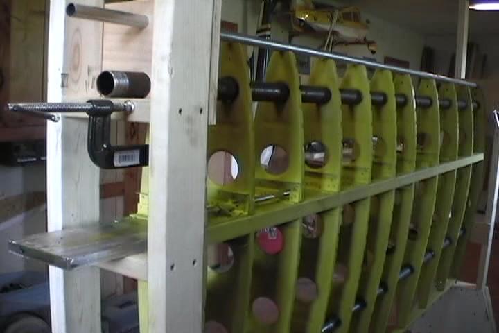
Attached wing jig to ceiling. 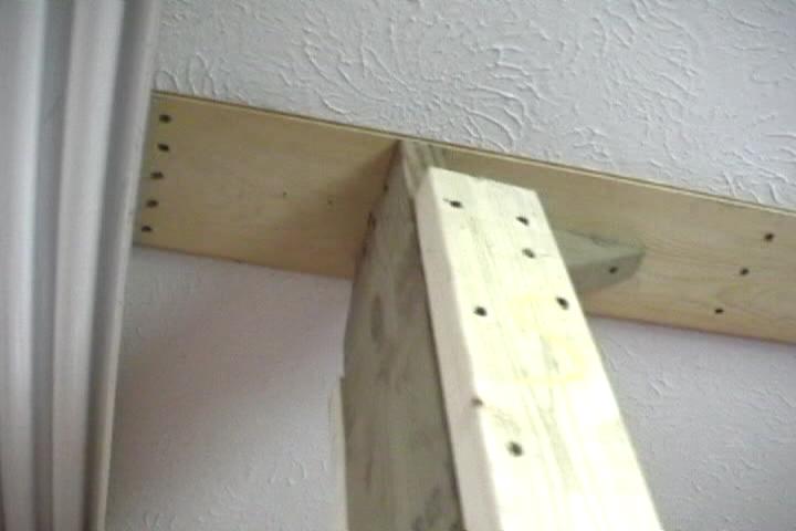
Putting in the 2" water pipe through lightening holes, The first rib I had to go through was too tight.Came to find out that that one lightening hole was smaller than all the rest. Opened it up with a little grinding with a scotchbrite wheel on the air grinder. 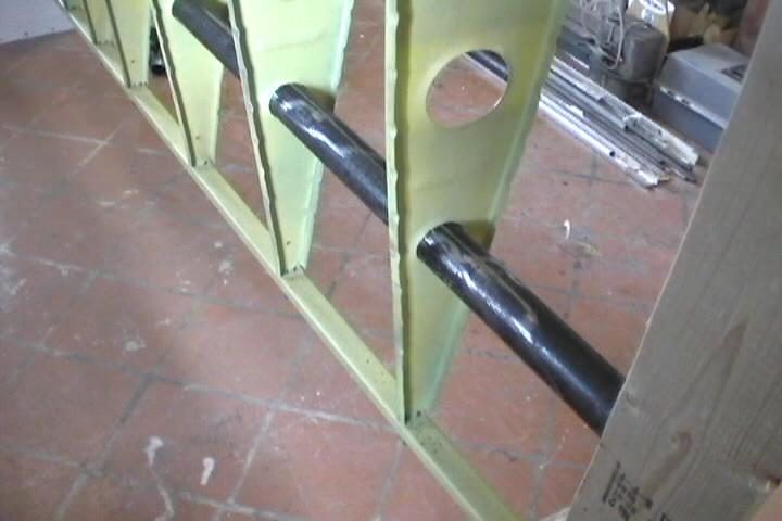
Slide tube assembly on front of spar. 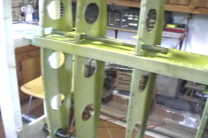
Slide tube assembly bolted in. 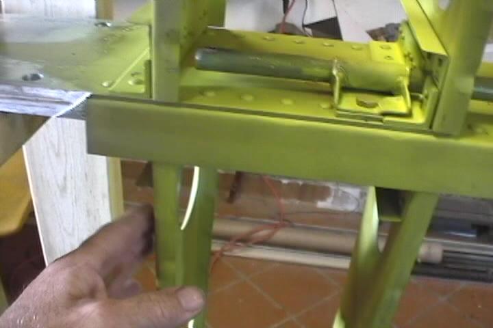
Wing fold tube rivetted in. 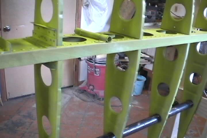
Leading edge conduit. Spacer between conduit and water pipe to correct for any sag in conduit. 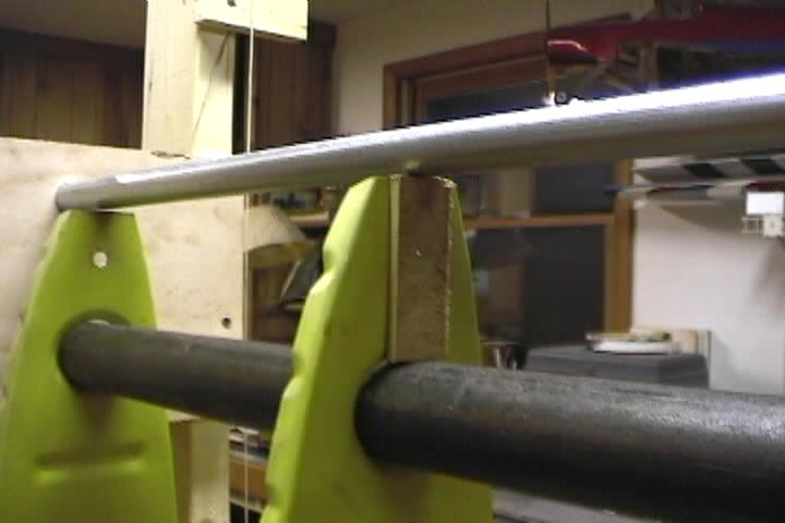
Plumb line at end of jig to make sure everything is aligned. 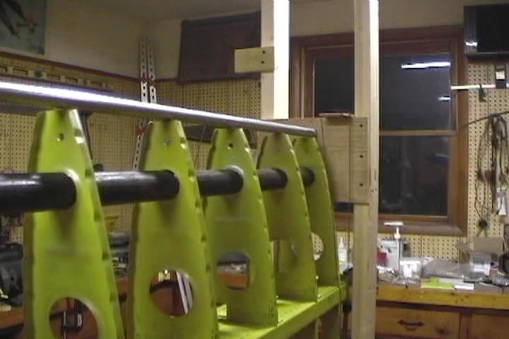
Cut and notched a piece of wood to support tip of spar in jig. 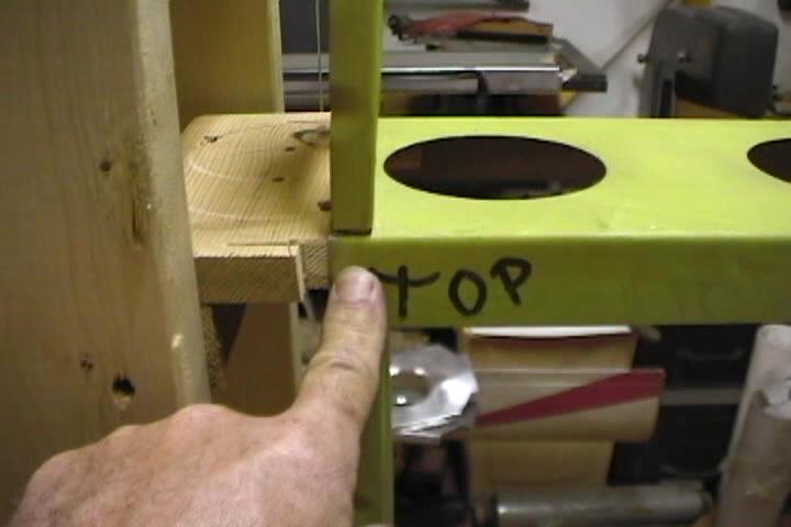
Bottom view of spar tip support. 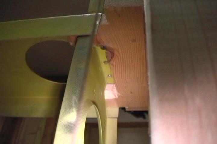
Aft spar securement in jig. 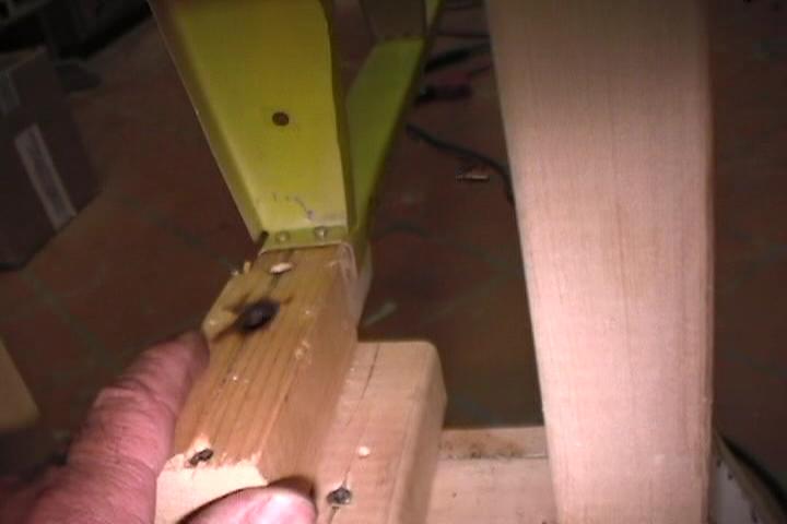
Leading edge conduit propped up small pieces of 1/4" plywood. 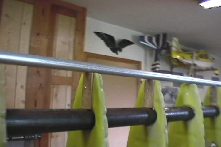
Made up a brace to help keep the ribs from moving while shifting and drilling wing skins. This one is on the nose ribs. 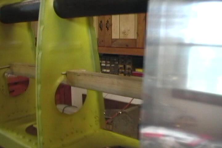
Made up a brace to help keep the ribs from moving while shifting and drilling wing skins. This one is on the main ribs. 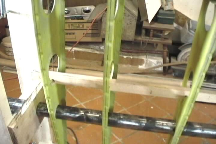
Initially drilled the hole for the leading edge conduit on the wrong centerline. Had to open up the original hole and made up these blocks of wood to hold it in the corrected position. Didn't catch this until putting the pre-bent skins on the jig. 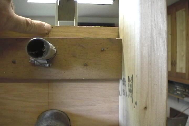
This is the wing tip rib drilled and clecoed. 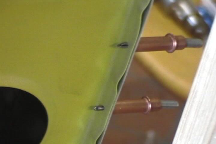
Leading edge conduit propped up with small pieces of 1/4" plywood to remove any sag.Not a good idea to heve 2 lines marked on rib flanges. You won't know which one to align with when looking through a 3/32" hole in the skin. 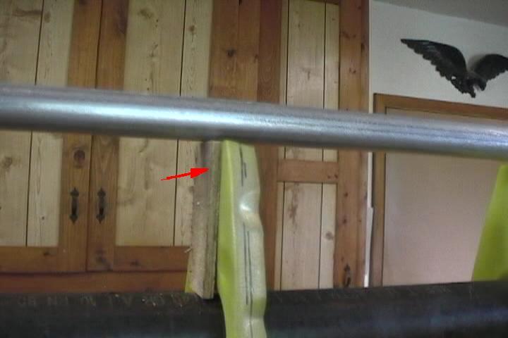
Seems like I already did this. I did. This is the other wing. 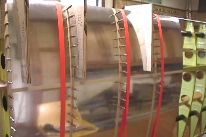
Here's the bracing again. Nose rib. 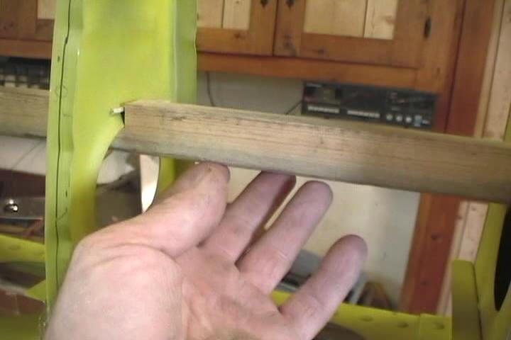
Bracing again. Aft rib. Second wing goes a little easier. 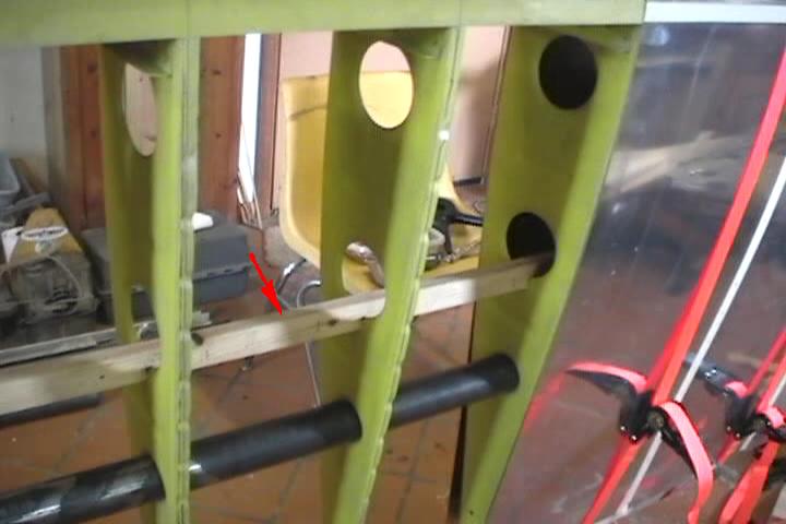
Cut-out for wing fold tube. 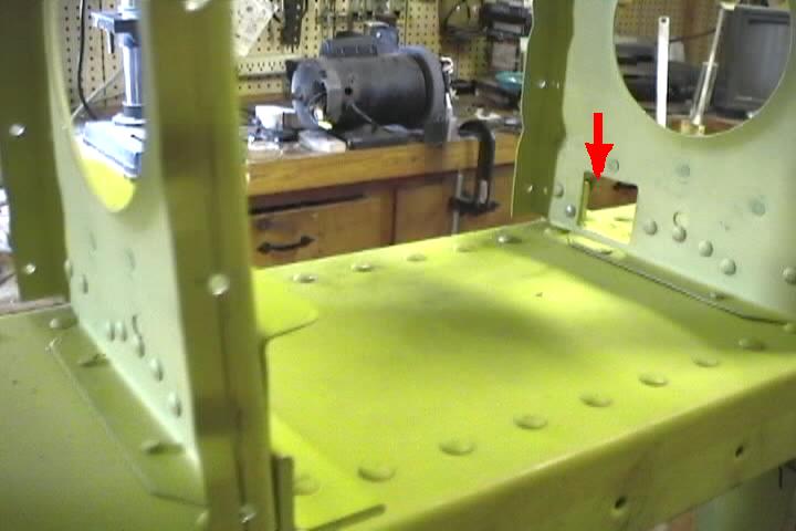
Used AN426 and An470 rivetts to assemble the ribs to the spars. Wanted practice using the rivet gun before tackling the more cosmetic wing skin rivets. 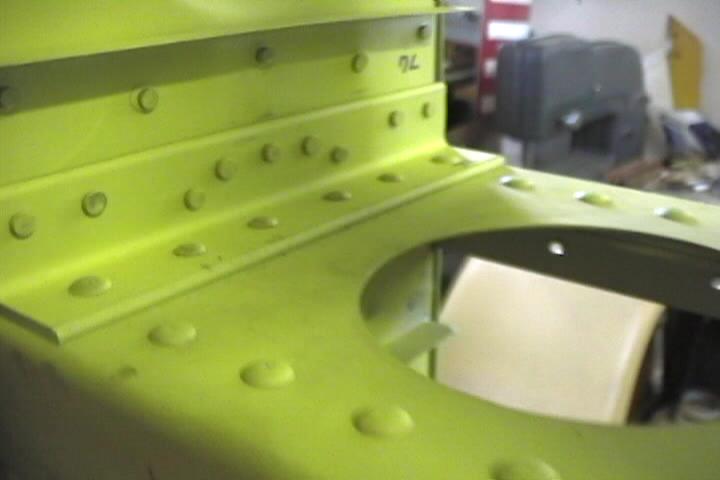
You might be able to notice the incorrect spacing of the rivets in the nose rib reinforcement angles here. Nice shot of the AN426 rivet shop heads here. 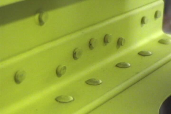
Running wiring through ribs before installing skins. Was considering tip lights. They say a lighted plane is a lot easier to spot even under VFR conditions. 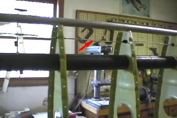
You can see how far off the leading edge conduit was from the enlarged hole. 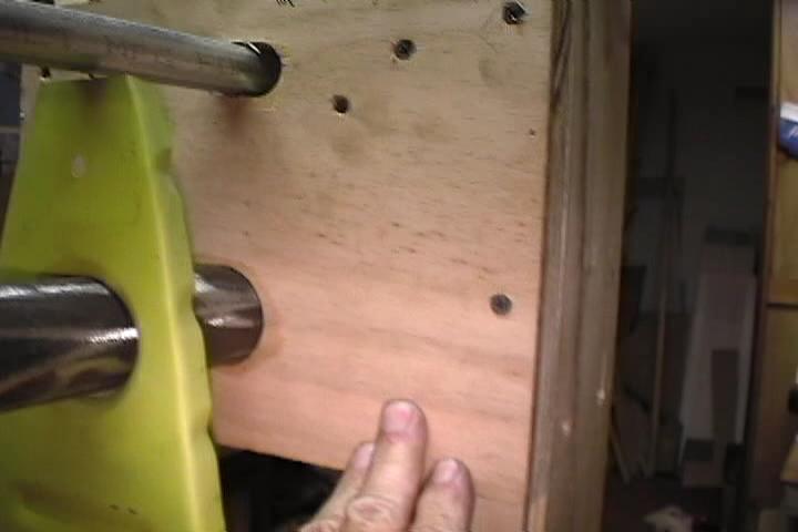
Correction block being located. 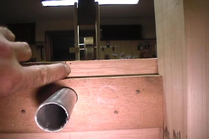
When I made up the water pipe holders I cut the pieces all from one sheet of plywood with the different centerlines marked the length of the plywood then cut up the 4 support pieces. 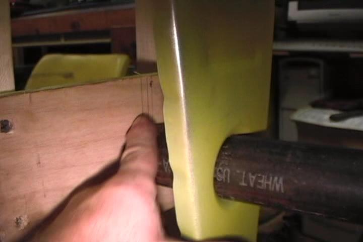
Plumming the water pipe supports. 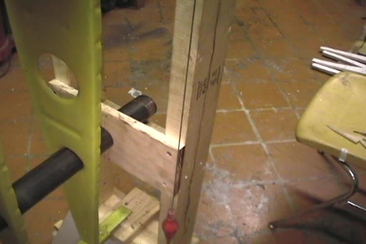
Used 2" black pipe instead of the more expensive galvanized pipe for jig. It has a black scale on it that flakes off as it goes through the lightening holes. 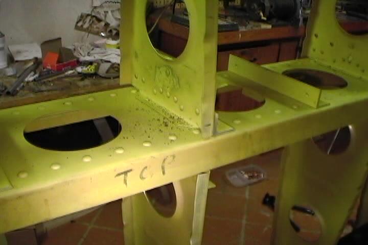
Marked centerlines on rib flanges. 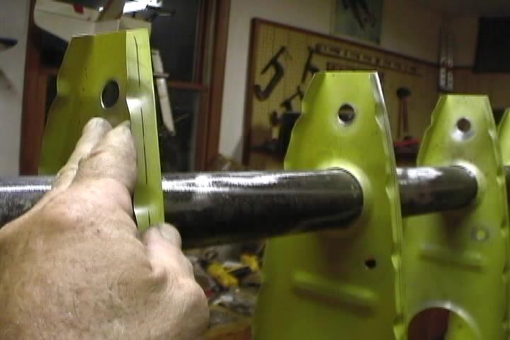
Had to enlarge guide pin holes to accept rubber bushings for pitot tubing. Had to use an air grinder with a coned shaped stone to enlarge holes. Been easier to enlarge holes before ribs where install on spar. 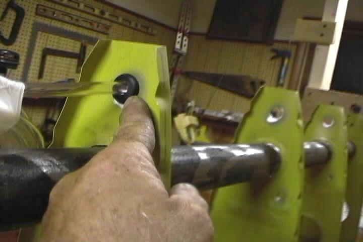
Also would have been easier to drill the holes for the wiring bushings before the ribs are installed on spar. Wasn't sure of the hole locations until the rib spar assembly was in the jig. 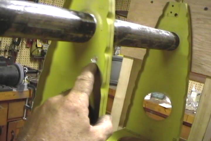
Another view of the hole locations for bushings. 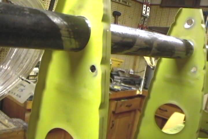
Hard plastic bushing for wiring. 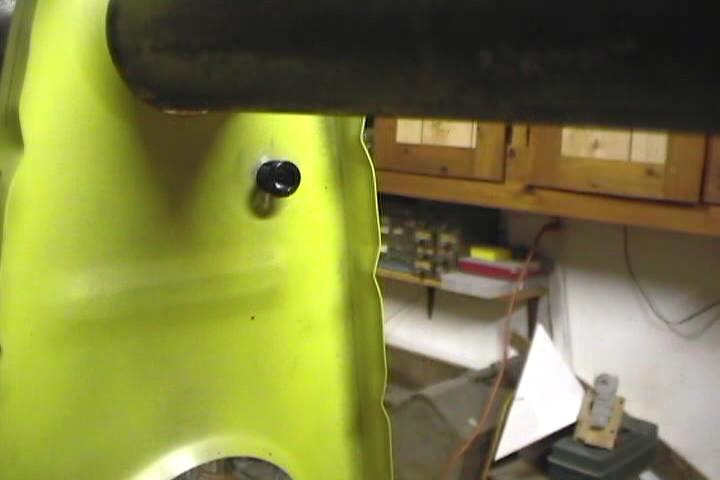
Measure from the tip edge to the center line on the rib flange. 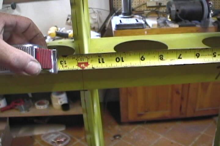
Clamped a piece of scrap .025" to the of the wing tip to take my measurements for the rib centers. 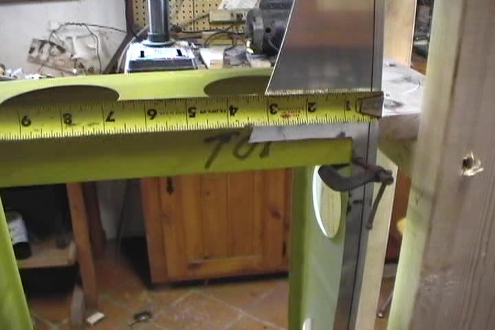
My rib flanges are a bit wider than 1/2". Gave me a little more to play with to keep rivet holes 1/4" from edge. 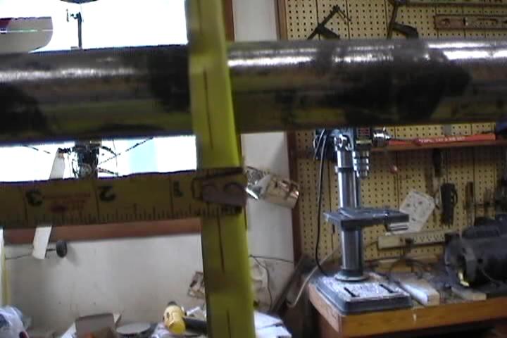
Used a screw in the guide pin hole to hold the pieces of 1/4" plywood supporting the sag in the leading edge conduit. 
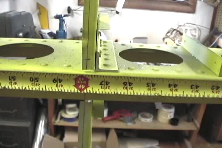
Measuring rib centers. 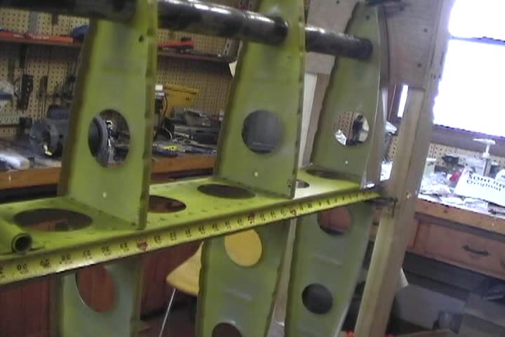
Got to make sure your ribs are in the center where the skins overlap. Should be 47 3/4" from tip to center of rib.